You’re back at the office. The flight went perfectly: calm winds, good light, solid overlap. The orthomosaic looks great. You export the GeoTIFF, load it into ArcGIS, and overlay it against the client’s existing survey data.
Then you see it. Your map is shifted 1.2 meters east. The coordinates look right on screen, but they’re wrong on the ground.
This is the moment most drone operators realize they’ve been building floating 3D models: technically beautiful, geographically worthless.
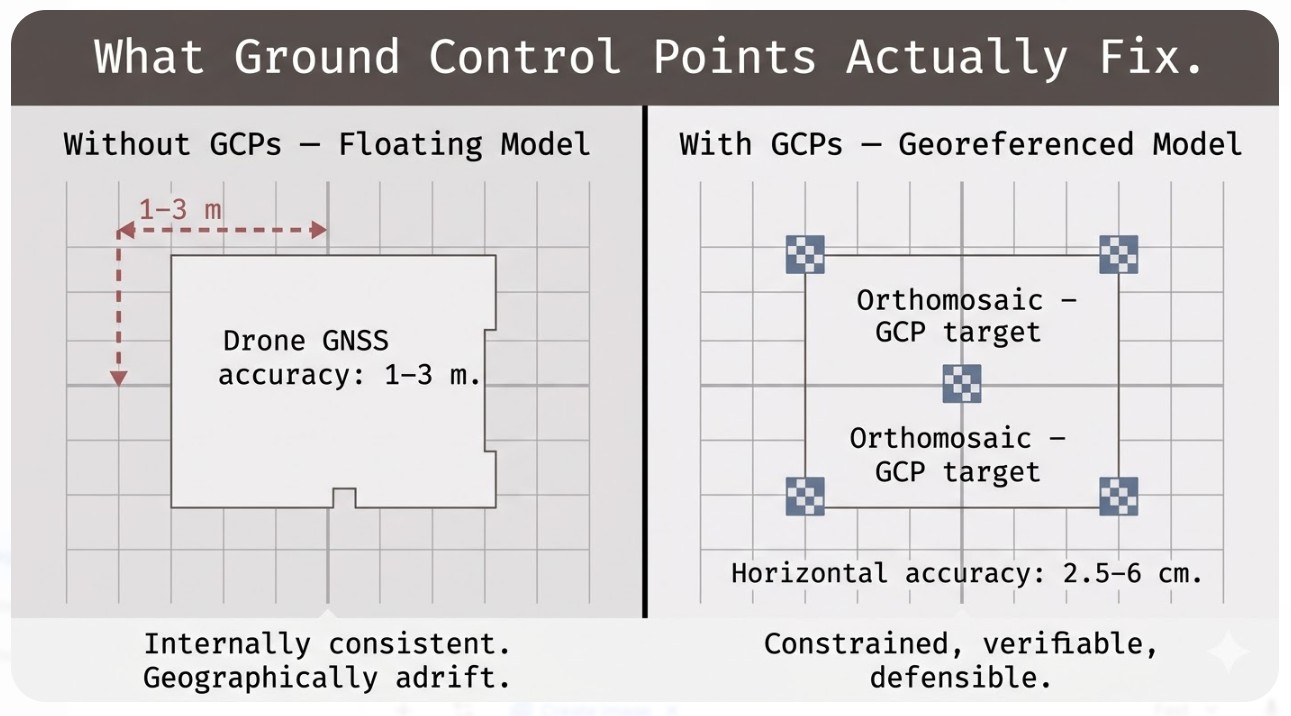
That shift isn’t an accident. It happens because you flew without adequate ground control, or without understanding how control points actually work. Your photogrammetry software built a model from camera positions estimated by consumer-grade GNSS, which tops out at 1–3 meters accuracy on a good day. The orthomosaic is internally consistent — every building and road in the right place relative to everything else — but the whole thing is adrift in geographic space.
This is what ground control points solve. Not perfectly, not magically, but systematically — and in a way you can actually defend to a client.
This article covers how many GCPs a drone survey actually needs, where to place them so they do real work, and the difference between control points and checkpoints — the distinction that separates professional drone mapping from hobbyist work.
What Are Ground Control Points?
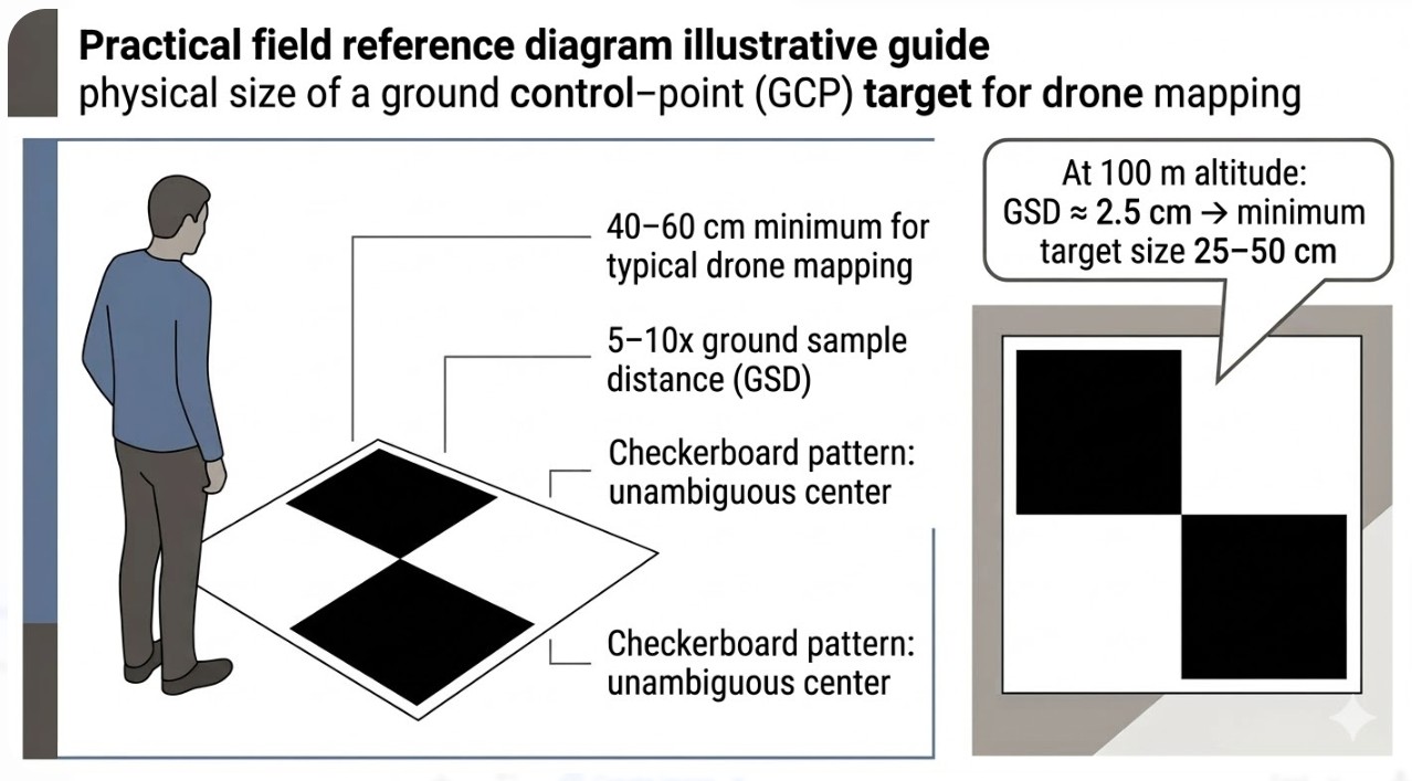
A ground control point is a physical target on the ground at a precisely known location. That’s it. Usually a marked square — checkerboard pattern, roughly 40–60 centimeters on a side — painted on asphalt or set up as a canvas tarp. The target itself isn’t the important part. The important part is the X, Y, and Z coordinate you’ve measured at that target’s center using survey-grade GNSS, a total station, or a properly calibrated RTK system.
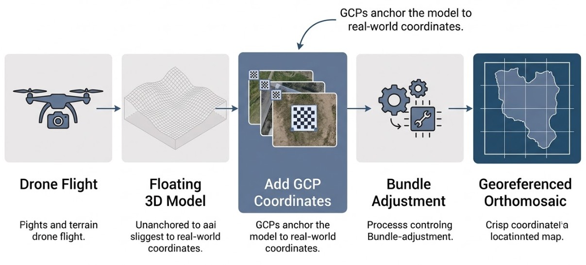
Here’s what happens during processing. Your drone captured hundreds of overlapping photos from different angles. The photogrammetry software — Pix4D, Agisoft Metashape, DroneDeploy, others — runs structure-from-motion (SfM) processing, which reconstructs a 3D model by finding matching points across overlapping images. This process is geometrically elegant but blind to geography. The software doesn’t know where north is. It doesn’t know the absolute scale of the model. It doesn’t know whether the elevation values are relative to sea level, a local benchmark, or just the lowest point in the survey area.
What SfM builds is a floating 3D model. All the spatial relationships within that model are correct — buildings and terrain features in the right place relative to each other — but the whole thing is unanchored. It could be shifted two meters east, rotated slightly, or scaled incorrectly, and the internal math would still be perfectly self-consistent.
GCPs anchor that floating model to the real world. When you feed the software your measured target coordinates, the processing engine runs bundle adjustment: a mathematical operation that stretches, rotates, and scales the 3D model until the projected position of each GCP in the imagery matches its known real-world coordinate. The more GCPs you provide, and the better they’re distributed, the more precisely the software can correct for positional and scale errors.
Without GCPs, your drone’s onboard GNSS bakes 1–3 meters of error into the output. With well-distributed GCPs, horizontal accuracy drops to 2.5–6 centimeters and vertical accuracy to 3–6 centimeters, depending on terrain, flight parameters, and equipment. For professional mapping — surveying, construction, environmental management, legal boundary work — that difference isn’t academic. It’s the difference between a deliverable and a liability.
How Many GCPs Does a Drone Survey Need?
Ask ten drone pilots how many GCPs they use and eight will say five. Ask why, and most will say “industry standard”: four corners, one in the middle. It works most of the time. It’s also often wrong.
The five-point standard came from practical experience and was picked up by the major software vendors. Pix4D recommends a minimum of 3 but suggests 5–10 for reliable results. Agisoft recommends at least 5. DroneDeploy suggests 4 as a non-RTK minimum. So yes, five is a reasonable starting point.
But the actual number depends on three things: survey area size, terrain complexity, and the accuracy class your client expects.
Under 5 acres: 5 well-distributed GCPs is genuinely adequate. The area is small enough that a single GCP constrains a large portion of the model, and you’re unlikely to have terrain variation that creates systematic errors in different zones.
5–50 acres: aim for 5–8 GCPs. This is where the five-point rule starts showing its limits. A single center point can’t constrain far corners equally well, especially on sites with interior features far from any control. Eight GCPs, well distributed, gives you coverage without unnecessary redundancy.
50–500 acres: 8–12 GCPs, spaced roughly 300 meters apart. At this scale, the geometry of your GCP network matters more than the absolute count. Clustering control points in one zone leaves the rest of the site underconstrained — which is worse than having fewer, better-placed points.
Over 500 acres: start with 1 GCP per 50 acres as a baseline, which works out to 10–20+ depending on the site. This is also where diminishing returns kick in. A 2020 study published in the MDPI Remote Sensing journal found that accuracy improves steeply up to about 12 GCPs, then flattens. Adding your 15th GCP does far less than adding your 6th.
Terrain complexity breaks all these rules.
If your survey area is flat — a parking lot, an agricultural field, a quarry at uniform elevation — and all your GCPs sit at roughly the same elevation, you’ve created a vertical constraint problem. The software has solid horizontal control from the GCP network but very few independent measurements on the vertical axis. The result is a systematic vertical error called the doming effect: the outer edges of the survey appear slightly higher or lower than the center, creating an artificial dome or bowl across the site. The model is internally consistent, but vertically skewed.
The fix: place GCPs at topographic highs and lows, not just wherever the ground is easy to measure. On a site with 20–30 meters of elevation change, your GCP network needs to span most of that range. A GCP at a hilltop and another in a valley give the software independent Z constraints in different parts of the model — and that’s what corrects vertical bias.
There’s one more case where the five-point rule falls apart completely: corridor mapping. Surveying a road, pipeline, or transmission line means your geometry is fundamentally different. You don’t have four corners and a center. You have a narrow strip, potentially kilometers long. For corridor work, stagger GCPs on alternating sides of the feature, keep maximum spacing to 300 meters, and place pairs of GCPs at each end. This almost never comes up in general drone training, but it’s essential for professional corridor surveys.
Where to Place GCPs: Distribution Over Density
Here’s the principle that separates experienced operators from those still figuring it out: even spatial distribution matters more than total count.
Think of anchoring a tent in wind. Weight down all four corners and the center might still flap. Place pegs at even intervals around the perimeter with one in the middle and the whole structure holds. Clustering your GCPs in one area — even if you have twelve total — is like piling all the pegs on one side. The rest of the tent flaps. The rest of your survey area is underconstrained.
I’ve seen operators with ten GCPs produce worse results than operators with five, solely because the ten were clustered. Distribution beats density every time.
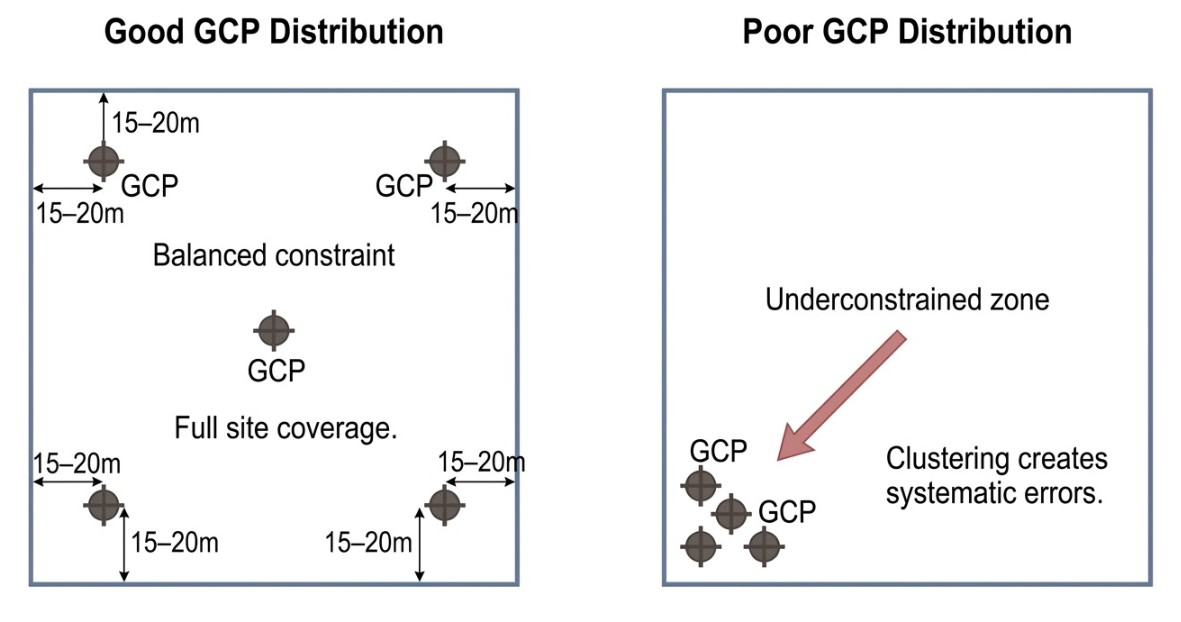
Pull GCPs inward from the survey boundary by 10–30 meters. This sounds counterintuitive but it’s critical. The edges of your survey are covered only by photos taken from high altitude at steep angles. GCPs positioned right at the boundary often appear in only one or two images, which limits how well the software can tie them to the surrounding model. GCPs set inboard, visible in multiple overlapping photos, provide stronger geometric constraints.
Place GCPs at topographic highs and lows, not just where the ground is convenient. On flat sites, this might mean targeting a modest rise and a slight depression. The vertical constraint matters, even when the elevation difference seems trivial.
Ensure clear sky view above each target. A GCP under a tree canopy or in a building’s shadow is a measurement error waiting to happen. GNSS struggles with partial sky coverage, multipath errors increase, and your coordinate is wrong before it ever reaches the model.
Set targets on stable ground. Loose soil, sand, or anything that might shift between measurement and flight invalidates that control point. A 5-centimeter movement after you’ve measured it can corrupt the entire model.
Keep GCPs clear of metal structures and fences. GNSS signal reflecting off metal causes multipath errors that degrade solution quality. If a site layout forces a GCP near a fence, use an RTK base station close by and run a long averaging window to work through the noise.
Make sure targets will be in direct sunlight during your flight window. Moving shadows across a target make it harder to identify the center precisely, and marking errors accumulate.
Spread GCPs across the entire survey area — even if that means some are in inconvenient terrain. Interior control is worth the extra effort.
GCPs vs. Checkpoints: The Distinction Most Operators Get Wrong
This is the most important section in this article. It’s where professional work separates from amateur work.
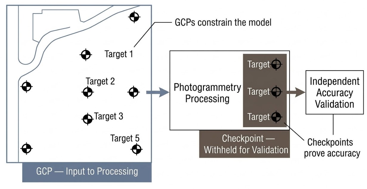
A ground control point is a measured coordinate you feed into the processing software. It becomes an input to the bundle adjustment calculation. The software uses it to constrain and correct the 3D model. When you designate a point as a GCP in Pix4D or Metashape, you’re telling the software: “I measured this location precisely. Use it to anchor the model.”
A checkpoint is a measured coordinate you deliberately withhold from processing. After the model is finalized, you compare the model’s calculated coordinates at that checkpoint location against the actual measured coordinates. That difference is your independent accuracy validation — the only number that actually proves your survey is correct.
This matters because the quality report your software generates — the one showing RMSE values and accuracy statistics — is not proof of accuracy. It’s an internal consistency check. The software is reporting how well the model fits the control points you gave it. If you fed it five GCPs and the RMSE is 2 centimeters, you’ve learned that the model is internally consistent to within 2 centimeters relative to those five points. You’ve learned nothing about accuracy anywhere else on the site.
Only checkpoints give you independent, auditable validation.
Here’s a concrete scenario. You fly a 20-acre site, set up five GCPs measured with RTK, process the imagery in Pix4D with all five designated as control, and get a horizontal RMSE of 1.8 centimeters and vertical RMSE of 2.4 centimeters. You export the orthomosaic and send it to the client.
What did that RMSE tell you? It told you those five GCP coordinates line up with your five measured coordinates to within 1.8 centimeters. But if you had a 20-meter blunder at your base station, every GCP would inherit that error. The entire model would be systematically wrong — and the RMSE would still read 1.8 centimeters.
If instead you’d measured seven points and withheld two as checkpoints, you could report: “Five ground control points achieved 1.8 cm horizontal RMSE. Two independent checkpoints validate 2.1 cm horizontal accuracy.” That’s a professional statement. It’s auditable. It’s defensible.
For a typical 20-acre survey: 5 GCPs plus 2 checkpoints. For a 100-acre project: 10 GCPs plus 3–5 checkpoints. DroneDeploy’s guidance suggests starting with a 2:1 ratio of GCPs to checkpoints, with at least 1 checkpoint per project regardless of size.
The most common mistake I see is importing all available measured coordinates as GCPs, leaving nothing for independent validation. More control seems better, but it’s strategically backward. You’re optimizing for a clean quality report rather than proof of accuracy.
Engineering firms, government agencies, and any client delivering data for legal or compliance purposes expect this distinction. They want checkpoint validation, not just a software report. It’s the mark of someone who actually takes accuracy seriously.
What About RTK and PPK Drones?
RTK and PPK technology corrects camera position to 1–3 centimeters instead of the consumer-grade 1–3 meters. For many operators, this raises the obvious question: do I still need ground control points for a drone survey?
The honest answer is: probably yes.
RTK and PPK correct the position of the GNSS antenna on the drone. But that antenna is physically separated from the camera lens by a few centimeters in three dimensions. The relative orientation between antenna and camera — called boresight misalignment — is small but not zero. Manufacturing tolerances, calibration drift, and slight airframe flex under load all introduce small angular offsets. Those offsets are usually millimeter-to-centimeter range, but when you’re mapping a 100-acre site from 120 meters altitude, small angular errors accumulate into larger positional errors across the area.
The result is typically a systematic vertical error. Research on PPK-only processing found that flights without ground control achieved vertical RMSE of approximately 5.5 centimeters. The same flights processed with just five well-distributed GCPs dropped that to approximately 2.6 centimeters. A factor-of-two improvement from five control points.
For survey-grade work with quality RTK/PPK equipment, a base station within 10–15 kilometers, multiple satellite constellations, and careful boresight calibration, you can sometimes operate without GCPs when your accuracy requirement is lenient — large-scale thematic mapping, environmental surveys where a 5-centimeter error is acceptable. But for engineering, construction, boundary work, or any project requiring independent accuracy validation, use at least 1–3 GCPs as ground truth anchors, even with RTK/PPK.
This is partly technical, partly professional. Technically, those few GCPs catch calibration drift and boresight errors. Professionally, they give you an independent reality check. You can report: “RTK camera positioning plus three independent ground control checkpoints validate accuracy to 2.8 centimeters.” That’s credible. “RTK alone” isn’t, even when the drone’s onboard system reports impressive numbers.
For legal, cadastral, or permit-required work, an RTK/PPK system without checkpoint validation isn’t acceptable. You need independent verification no matter how good the drone’s GNSS is.
Common GCP Mistakes That Kill Drone Survey Accuracy
Clustering GCPs in convenient locations. I’ve worked on sites where all five GCPs were bunched in one corner because that’s where site access was and the ground was flat. Three-quarters of the site was underconstrained. The orthomosaic had systematic errors in the remote zone that no amount of post-processing could fix. Fewer, better-distributed GCPs would have been more accurate.
All GCPs at the same elevation on flat terrain. This creates the doming effect. The software has no independent vertical constraints in different parts of the model, so it bends the vertical axis to fit the control you gave it. Place GCPs at topographic highs and lows — even modest ones.
Not designating any checkpoints. Without checkpoints, you have no independent proof of accuracy. You cannot defend your results if they’re questioned. Withhold at least one or two points from processing on every project.
Marking GCPs in too few images. Pix4D’s minimum is two images per GCP, but best practice is 5–8 overlapping images with the target clearly visible. GCPs at the edge of the flight area often appear in only one or two photos. When those two images are shot from nearly the same angle, the observations are nearly collinear — geometrically weak — and the constraint is poor.
Ambiguous target center. Shadows, glare, or blurry edges make it impossible to mark the precise center. If you can’t identify the center within a pixel or two, marking errors accumulate into real error. Use high-contrast checkerboard targets in clean, direct lighting.
Base station not on a known benchmark. If your RTK base station position is wrong, every GCP is wrong. All your control points become internally consistent with each other but absolutely wrong relative to the real world. Always verify the base station is on a known survey benchmark or has been independently verified with a second receiver.
Targets disturbed between measurement and flight. Measure a GCP at 9 a.m., and wind or a crew member shifts it 5 centimeters before the 2 p.m. flight — your measured coordinate no longer matches the target in the imagery. Mark targets with paint or fixed markers that won’t move between measurement and collection.
Field Protocol: Equipment and Documentation
Targets
Rigid PVC checkerboard panels are ideal for repeated use — durable, consistent, and they last for years. Laminated vinyl or canvas tarps work fine for single-use projects. Minimum target size is 5–10 times the ground sample distance (GSD) of your flight. At 100 meters altitude with a typical drone camera, GSD is roughly 2.5 centimeters, so your target needs to be at least 40–60 centimeters on a side. The checkerboard pattern is preferred because the center point is unambiguous regardless of rotation or lighting angle.
GNSS Measurement
Use survey-grade RTK equipment: Emlid Reach RS2, Trimble, Leica, or equivalent. Consumer-grade GNSS on a smartphone isn’t acceptable — accuracy sits at 3–5 meters. For each GCP, position the rover directly over the target center and wait for an RTK Fixed solution (not Float), which confirms carrier-phase ambiguity resolution has converged. Collect a 30–60 second average to smooth noise. Check the PDOP value and aim for below 3.0. Above 5.0, wait or reposition away from obstructions.
Documentation
For each GCP, record:
- Point ID
- Coordinates (easting/northing/elevation, or lat/long/height)
- Antenna height above the target (measure precisely every time — antenna height errors propagate directly into vertical error)
- GNSS equipment model
- Solution quality (RTK Fixed, Float, or autonomous)
- Date and time of measurement
- Photo of the target and surrounding area
That documentation is what saves you when accuracy comes out worse than expected. Reviewing antenna height measurements and solution qualities usually reveals the culprit.
Final Thoughts
Ground control points solve a fundamental problem in drone mapping: they anchor the floating 3D model that photogrammetry builds to real-world coordinates. Without them, your data is internally consistent but geographically adrift — shifted by 1–3 meters depending on your drone’s GNSS accuracy.
The guidance is straightforward. Start with five well-distributed GCPs for any drone survey of reasonable size. Scale up to 8–12 for larger or more complex terrain, spacing them roughly 300 meters apart and ensuring coverage at topographic highs and lows. Pull them slightly inward from the boundary so they appear in multiple overlapping images. And always withhold 1–2 points as checkpoints for independent accuracy validation.
That checkpoint distinction is the mark of professional work. The difference between “my software says I’m accurate” and “I’ve independently verified I’m accurate.” For clients whose decisions depend on those coordinates — engineering firms, government agencies, anyone using the data for legal or compliance purposes — that distinction is what makes your deliverable credible.
FAQ
How many GCPs do I need for a drone survey?
For most surveys under 5 acres, five well-distributed GCPs is adequate. For 5–50 acre sites, aim for 5–8. For 50–500 acres, use 8–12 spaced roughly 300 meters apart. The count matters less than distribution — clustered GCPs leave parts of the site underconstrained, which is worse than having fewer, better-placed points.
Do I need GCPs with an RTK drone?
For most professional work, yes. RTK corrects the antenna position on the drone, but small boresight misalignment between the antenna and camera lens can create systematic vertical errors — especially across large sites. Research shows that adding just five GCPs to a PPK flight can cut vertical RMSE roughly in half. For legal, cadastral, or permit-required projects, checkpoint validation is required regardless of the drone’s GNSS capability.
What is the difference between a GCP and a checkpoint?
A GCP is a measured coordinate fed into the photogrammetry software as an input to bundle adjustment — it constrains and corrects the model. A checkpoint is a measured coordinate deliberately withheld from processing, then used after the fact to independently validate accuracy. The RMSE in your software’s quality report only reflects how well the model fits the GCPs you gave it. Only checkpoints provide independent, auditable proof that your survey is accurate.
How accurate can a drone survey be with GCPs?
With well-distributed GCPs measured using survey-grade RTK equipment, horizontal accuracy typically reaches 2.5–6 centimeters and vertical accuracy 3–6 centimeters. RTK/PPK drones with GCPs can push closer to 2–3 centimeters horizontal under good conditions. Without GCPs, you’re relying on the drone’s consumer-grade GNSS, which introduces 1–3 meters of absolute error.