



Updated October 2026: We rewrote the georeferencing steps to match COLMAP’s documentation (COLMAP has no ground-control input, and model_aligner takes per-image camera positions, with —ref_is_gps 0 for projected coordinates), moved GCPs to a separate point-pair transform and checkpoint validation, clarified that three non-collinear points is the mathematical minimum and five GCPs our recommendation, fixed the pose_prior_mapper flags (and added the mkdir it needs), renamed the guided-matching flag to COLMAP 4.x’s —FeatureMatching.guided_matching, and corrected the Nerfstudio model and output paths. Nerfstudio converts camera poses to float32 when it loads them, so projected or ECEF coordinates lose precision before training starts; the tutorial now trains in a local ENU frame or with a local origin subtracted, and adds the origin back in float64 after export. We also corrected a misattributed study (now Tsukamoto et al., 2025), removed an unverifiable “2–3x” noise figure, stated GeoRefGS’s result as reported (distance errors below 5.4 cm), noted that ns-export pointcloud —save-world-frame reverses the dataparser transform for point clouds, limited the export script to point clouds and PLY meshes (it keeps faces and rotates normals; splats need more), corrected Nerfstudio’s normalized space to [-1, 1]³, and dated pose_prior_mapper to COLMAP 3.11.0.
You’ve captured 400 drone images of a construction site with your RTK-equipped Mavic 3 Enterprise. The photogrammetric point cloud is done — solid, validated, survey-grade. But the client also wants an immersive 3D walkthrough for the project stakeholders who don’t read point clouds. You’ve heard NeRF can do that. The question is whether you can build one that actually ties to real-world coordinates — not just a pretty floating scene in arbitrary space.
The answer is yes. But not out of the box, and not without understanding where the georeferencing actually lives in the pipeline. Every NeRF framework — Nerfstudio, Instant NGP, Luma AI — operates in scene-local coordinates by default. Getting from scene-local to WGS84 or a projected CRS requires deliberate steps at capture, processing, and export. Skip any of them and you get a visually impressive model that can’t be placed on a map.
This tutorial walks through the full workflow: capture requirements, COLMAP geo-registration, Nerfstudio training, georeferenced export, and accuracy validation. The pipeline has been validated on sites ranging from roughly 0.5 to 4 hectares. It works — with caveats worth being specific about.
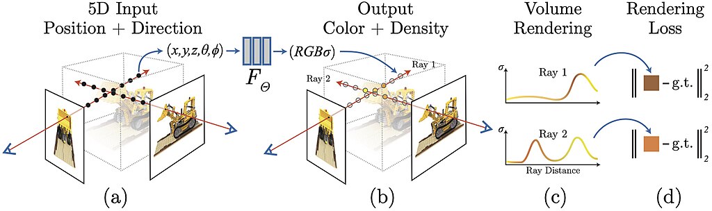 Mildenhall et al. (2020), from the original NeRF paper repository, MIT License
Step 1: Plan the Drone Capture for NeRF
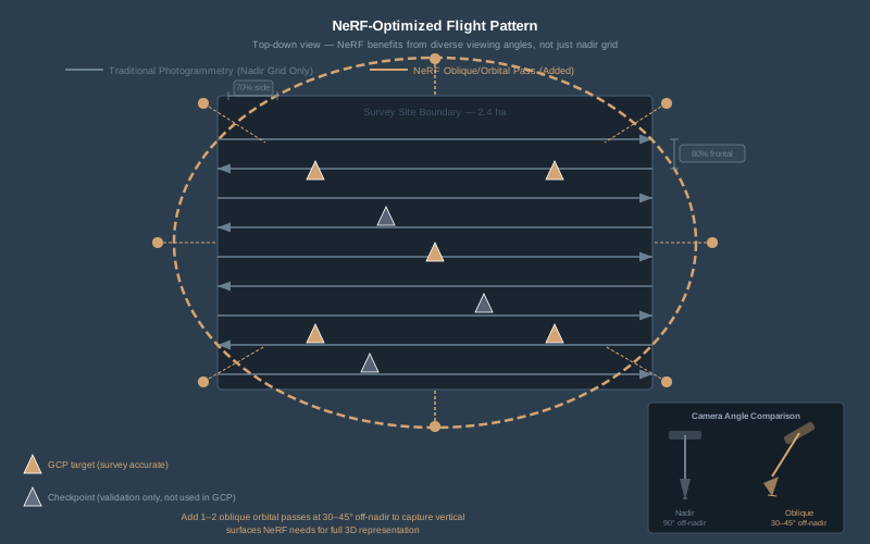
NeRF reconstruction is not the same as photogrammetric reconstruction, and your flight plan needs to reflect that. Traditional photogrammetry wants consistent nadir imagery with controlled overlap. NeRF wants diverse viewing angles — the more varied the perspectives, the better the volumetric representation.
Flight parameters that matter:
- Overlap. 80% frontal, 70% side — minimum. NeRF is more sensitive to coverage gaps than photogrammetry because it needs to reconstruct view-dependent appearance, not just geometry. At 60% frontal overlap, COLMAP will reconstruct camera poses but the NeRF will have artifacts in under-observed regions.
- Oblique passes. Fly at least one orbital or crosshatch pass at 30-45 degrees off nadir. This is where NeRF pulls ahead of traditional photogrammetry for visualization — oblique views capture vertical surfaces (building facades, retaining walls, cut slopes) that nadir-only missions miss entirely. Two oblique passes at different altitudes is better.
- Altitude. 60-90 meters AGL for site-scale scenes (2-5 hectares). Lower is higher resolution but exponentially more images. At 75m AGL with a Mavic 3 Enterprise (12.8mm lens), ground sampling distance is roughly 2 cm/pixel — more than sufficient for NeRF training.
- Exposure. Manual or shutter priority. NeRF is sensitive to exposure variation between frames — auto-exposure creates inconsistent lighting that the network interprets as view-dependent effects rather than what it actually is: your camera hunting. Lock ISO, set shutter speed for the conditions, and let it ride.
- Image count. 300-800 images for a 2-5 hectare site. More images means longer COLMAP processing and longer training but better reconstruction. Under 200 images and COLMAP starts struggling with feature matching on large outdoor scenes.
RTK or PPK geotagging is non-negotiable. If you want georeferenced output, you need georeferenced input. Autonomous phone-GPS geotags at 2-5 meter accuracy are useless for anything beyond rough scene placement. RTK gives you 1-3 cm positions in the EXIF data; PPK gives you the same after post-processing. Either works. The positions don’t need to be perfect — they need to be consistent and in a known datum.
Common combinations: DJI Mavic 3 Enterprise with RTK for urban sites, and PPK post-processing with an Emlid RS3 base for remote work. Both produce usable geotags for this pipeline.
Step 2: Set GCPs for Georeferencing and Validation
Ground control points serve two purposes in a NeRF workflow: they let you check, and if needed correct, the georeferencing that COLMAP derives from your camera positions, and they give you something to validate against after export.
GCP target design. Standard photogrammetry targets work fine — 12x12 inch checkerboard or circular coded targets, high contrast against the ground surface. Nothing special is needed: neither the neural network nor COLMAP treats a GCP differently from any other ground feature. COLMAP has no ground-control input at all. Its geo-registration works from camera positions (your RTK/PPK geotags), so the targets only matter when you identify them yourself in the reconstruction (Step 3, Option C) and at validation (Step 7).
Distribution. Three non-collinear points is the mathematical minimum for a 3D similarity transform (rotation, translation, scale). This tutorial’s working minimum is five GCPs — corners and center of the site, well-distributed in X, Y, and Z — so that one bad point shows up as a large residual instead of silently skewing the fit. If you have significant terrain variation, get a GCP at your highest and lowest elevations. Then place 3-5 additional points as independent checkpoints — these are not used in the georeferencing step. They exist solely to validate accuracy after export.
Survey method. RTK rover on a known control network, or PPK observations with 180-second occupations on each point. Record in the project datum — if the deliverable is NAD83/State Plane, survey your GCPs in NAD83/State Plane. Datum transformations at the GCP stage introduce error that propagates through the entire pipeline.
Record the coordinates in a CSV, one row per point, in the project CRS. Keep GCPs and checkpoints in separate files so checkpoints never leak into the transform:
# gcps.csv: id, easting, northing, elevation (project CRS, metres)
GCP_01,425789.123,4512301.456,312.78
GCP_02,425812.456,4512289.012,311.92
GCP_03,425801.789,4512315.678,313.45
These are ground coordinates, not camera positions, so they do not go into COLMAP’s model_aligner (see Step 3).
Step 3: Process Camera Poses with COLMAP
COLMAP is the backbone. Every NeRF framework that works with arbitrary image sets uses COLMAP (or a fork of it) to estimate camera poses through Structure-from-Motion. The quality of your NeRF lives and dies with the quality of your COLMAP reconstruction.
Install COLMAP 4.x. The pose_prior_mapper (introduced in COLMAP 3.11.0, November 2024) directly integrates GPS priors during reconstruction — a significant improvement over the old workflow of reconstructing first and aligning second.
Option A: GPS-Prior Reconstruction (Recommended)
If your images have RTK/PPK coordinates in the EXIF data, COLMAP 4.x can use them as pose priors during the reconstruction itself. This is cleaner than the legacy two-step approach.
# Feature extraction — COLMAP reads GPS from EXIF automatically
colmap feature_extractor \
  --database_path project/database.db \
  --image_path project/images \
  --ImageReader.camera_model OPENCV \
  --ImageReader.single_camera 1

# Feature matching
colmap exhaustive_matcher \
  --database_path project/database.db \
  --FeatureMatching.guided_matching 1

# Reconstruction with GPS pose priors (the output directory must exist)
mkdir -p project/sparse
colmap pose_prior_mapper \
  --database_path project/database.db \
  --image_path project/images \
  --output_path project/sparse \
  --overwrite_priors_covariance 1 \
  --prior_position_std_x 0.03 \
  --prior_position_std_y 0.03 \
  --prior_position_std_z 0.05
COLMAP 3.12 and earlier spell the matching flag --SiftMatching.guided_matching; 3.13 and 4.x renamed it --FeatureMatching.guided_matching.
The prior_position_std values tell COLMAP how much to trust your GPS positions. They only take effect with --overwrite_priors_covariance 1; without it, COLMAP uses the covariance stored with each prior in the database, and EXIF-derived priors carry none, so it falls back to 1 m. For RTK-fixed positions, 0.03 meters (3 cm) horizontal and 0.05 meters (5 cm) vertical is realistic. For PPK-processed positions, same values. For phone GPS, use 3.0-5.0 meters — but at that point, you’re not really georeferencing.
COLMAP converts GPS priors to a local East-North-Up frame whose origin is the first image’s GPS position, so the output model is in metres in that ENU frame. Keep a note of that origin; you need it to convert exports back to latitude/longitude or into a projected CRS.
Option B: Reconstruct Then Align (Legacy Workflow)
If your COLMAP version doesn’t support pose_prior_mapper, or you want more control over the alignment:
# Standard reconstruction
colmap automatic_reconstructor \
  --workspace_path project \
  --image_path project/images

# Geo-register to per-image camera positions in a projected CRS
mkdir -p project/sparse/0_georef
colmap model_aligner \
  --input_path project/sparse/0 \
  --output_path project/sparse/0_georef \
  --ref_images_path project/camera_positions.txt \
  --ref_is_gps 0 \
  --alignment_type custom \
  --alignment_max_error 0.3
model_aligner does not take ground control. The reference file lists camera centres: one line per image, the image name followed by that camera’s X Y Z, which you export from the RTK/PPK geotags or the PPK event file, converted to the project CRS (save it as camera_positions_crs.txt; the step below turns it into project/camera_positions.txt):
DJI_0001.JPG 425731.412 4512287.905 387.21
DJI_0002.JPG 425731.398 4512302.118 387.19
DJI_0003.JPG 425731.420 4512316.342 387.24
With --ref_is_gps 0 the coordinates are used as-is (--alignment_type custom is the default), which is what you want for projected easting/northing/elevation. If you would rather keep latitude, longitude and ellipsoidal height, list them in that order with --ref_is_gps 1, and COLMAP converts them to ENU with the first image as origin (--alignment_type enu) or, with any other alignment type (including the default custom), to ECEF. --alignment_max_error is the RANSAC inlier threshold in the units of your reference coordinates; the COLMAP docs’ example uses 3.0, and RTK-grade camera positions justify a much tighter value.
Subtract a local origin before you align. Nerfstudio converts every camera pose to 32-bit floats when it loads the dataset (nerfstudio_dataparser.py), before it centers and scales anything. A float32 value near a 4,512,000 m northing can only land on 0.5 m steps, and near a 425,000 m easting on 3 cm steps, so projected or ECEF camera positions are already rounded when training starts, and no export script can recover what was lost. Keep the numbers small instead. Either use latitude/longitude with --ref_is_gps 1 --alignment_type enu, or pick a round origin near the site, subtract it from every camera position, and write it down:
# Raw CRS positions -> local offsets (origin 425000 E, 4512000 N, 0 m)
awk '{printf "%s %.3f %.3f %.3f\n", $1, $2-425000, $3-4512000, $4}' \
  camera_positions_crs.txt > project/camera_positions.txt
The aligned model is then in project-CRS metres minus that origin, and Step 5 adds the origin back in float64.
The aligner computes a 3D similarity transformation (rotation, translation, scale) from COLMAP’s arbitrary frame to those camera positions, using RANSAC to reject outliers, and logs the mean and median camera-position error after alignment. It needs at least three images with reference positions; a full flight gives it hundreds.
Option C: Tie the Model to Your GCPs
Options A and B georeference through the camera positions. If your geotags are not RTK-grade, or you want the surveyed ground control to define the frame, add a GCP step. COLMAP has no native GCP input, so this happens outside it:
- Find each GCP target in the exported point cloud (Step 5, after the local origin has been added back, so it is in the same CRS as
gcps.csv) and record its coordinate. - Load
gcps.csvas a point cloud in CloudCompare, then use Tools > Registration > Align (point pairs picking) with adjust scale enabled, picking the same GCPs in the same order in both clouds. It estimates a similarity transform and reports the residual RMS of the picked pairs. Three non-collinear pairs is the mathematical minimum; use all five or more. - Inspect the per-point residuals. One GCP far off the others is usually a mis-picked target or a typo in the coordinates.
- Save the transform and apply it to every product you export. Keep the checkpoints out of this step.

Verify the reconstruction. Open the sparse model in COLMAP’s GUI. Check that all cameras registered (compare image count in vs. registered count). If more than 5% of images failed to register, your overlap was insufficient or there’s a lighting/exposure problem in a section of the flight. Look at the sparse point cloud — it should roughly match your site geometry. If it looks like abstract art, something went wrong.
Step 4: Convert to Nerfstudio Format and Train
Nerfstudio is the most accessible open-source framework for training NeRFs from arbitrary image sets. It reads COLMAP output directly.
# Convert COLMAP output to Nerfstudio format
ns-process-data images \
  --data project/images \
  --output-dir project/nerfstudio \
  --colmap-model-path "$PWD/project/sparse/0_georef" \
  --skip-colmap
Pass --colmap-model-path as an absolute path: Nerfstudio resolves a relative path against --output-dir, so project/sparse/0_georef would point at project/nerfstudio/project/sparse/0_georef. If you used Option A, point it at project/sparse/0 instead. The --skip-colmap flag tells Nerfstudio to use your existing COLMAP reconstruction instead of running its own. This is critical — you already did the georeferenced reconstruction in Step 3. Letting Nerfstudio re-run COLMAP would throw away your geo-registration.
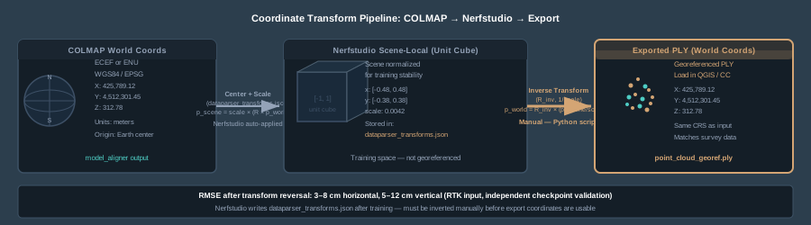
This produces a transforms.json file containing camera poses in Nerfstudio’s coordinate convention (OpenGL: +X right, +Y up, +Z back). The conversion from COLMAP’s OpenCV convention (+X right, +Y down, +Z forward) is handled automatically. But here’s the detail that matters for georeferencing: Nerfstudio also applies a centering transform and scale factor so the camera positions fit inside a [-1, 1]³ box, a cube 2 units across. These transforms are stored in dataparser_transforms.json after training. You need them later to reverse-transform your exports back to real-world coordinates.
Choose Your Method
# Nerfacto — general purpose, good quality, reasonable speed
ns-train nerfacto --data project/nerfstudio

# Splatfacto — 3D Gaussian Splatting, faster training and real-time rendering
ns-train splatfacto --data project/nerfstudio

# Instant-NGP — fastest training, lower quality on large scenes
ns-train instant-ngp --data project/nerfstudio
For drone survey scenes, I use Nerfacto when I need the highest geometric quality for point cloud export, and Splatfacto when the deliverable is a real-time viewer for stakeholder presentations. Instant-NGP trains in minutes but the geometry on large outdoor scenes doesn’t hold up for measurement.
Training time. Nerfacto on a 500-image drone dataset: 2-4 hours on an RTX 4090, 6-10 hours on an RTX 3080. Splatfacto is faster — roughly half. Plan accordingly.
Step 5: Export Georeferenced Products
This is where most tutorials stop, and where the actual work of georeferencing begins.
Nerfstudio exports point clouds and meshes in scene-local coordinates — the normalized [-1, 1]³ space it used during training. To get back to real-world coordinates, you need to reverse the transforms that Nerfstudio applied, then add back the local origin you subtracted in Step 3. For point clouds, Nerfstudio can do the reversal itself; for meshes, you do it with a script.
ns-train writes each run to outputs/<experiment>/<method>/<timestamp>/, where the experiment name defaults to the name of the data folder (nerfstudio here) and the timestamp looks like 2026-10-25_142233. Use your run’s folder wherever <timestamp> appears below.
Export the Point Cloud
# Export dense point cloud as PLY
ns-export pointcloud \
  --load-config outputs/nerfstudio/nerfacto/<timestamp>/config.yml \
  --output-dir exports/ \
  --num-points 1000000 \
  --remove-outliers True \
  --normal-method open3d \
  --save-world-frame True
--save-world-frame True applies the inverse dataparser transform to the point positions before writing the PLY, so the points come out in the frame you trained in: the local ENU frame, or project-CRS metres minus your local origin. Those coordinates are in the hundreds of metres, where float32 is precise to well under a millimetre. It does not rotate the normals, and it does not know about your local origin, so run the script below with SCENE_SPACE = False to finish the job.
Export a Mesh
# Export a mesh using TSDF fusion
ns-export tsdf \
  --load-config outputs/nerfstudio/nerfacto/<timestamp>/config.yml \
  --output-dir exports/ \
  --target-num-faces 500000 \
  --resolution 512
This writes tsdf_mesh.ply in scene-local space (plus a textured OBJ when texturing is enabled, which the script below does not handle).
Reverse the Dataparser Transforms
Meshes have no world-frame export option, and a point cloud exported without --save-world-frame is still in Nerfstudio scene-local space. To recover real-world coordinates:
- Read
dataparser_transforms.jsonfrom the training output directory. It contains a 3x4 transform matrix and a scale factor. - Invert the transform. Every point in the exported PLY was transformed as:
p_scene = scale * (R * p_world + t). To reverse:p_world = R_inv * (p_scene / scale - t). - Apply the inverse to every vertex, rotate any normals by
R_inv, and add the local origin back in float64.
Here’s a Python script that does this for a point-cloud PLY or a PLY mesh such as tsdf_mesh.ply (it keeps the faces). It is not enough for a splat PLY: each Gaussian’s scale_* values must also be rescaled and its rot_* quaternion and spherical-harmonic coefficients rotated, which this script does not do.
import json
import numpy as np
from plyfile import PlyData, PlyElement

RUN = "outputs/nerfstudio/nerfacto/<timestamp>"  # your training run
IN_PLY = "exports/point_cloud.ply"
OUT_PLY = "exports/point_cloud_georef.ply"
SCENE_SPACE = True  # False if you exported with --save-world-frame True
# Local origin subtracted in Step 3 (Option B); zeros for Option A's ENU frame
ORIGIN = np.array([425000.0, 4512000.0, 0.0])

with open(f"{RUN}/dataparser_transforms.json") as f:
    meta = json.load(f)
transform = np.array(meta["transform"], dtype=np.float64)  # 3x4 matrix
scale = float(meta["scale"])
R, t = transform[:, :3], transform[:, 3]
R_inv = np.linalg.inv(R)

ply = PlyData.read(IN_PLY)
vertex = ply["vertex"].data
names = vertex.dtype.names
points = np.column_stack([vertex["x"], vertex["y"], vertex["z"]]).astype(np.float64)

# Reverse transform: scene-local -> training frame
if SCENE_SPACE:
    points = (R_inv @ (points / scale - t).T).T
# Add the local origin back; keep float64, since float32 at
# projected-CRS magnitudes (millions of metres) is spaced 0.5 m apart
points += ORIGIN

dtype = [(n, "f8") if n in ("x", "y", "z") else (n, vertex.dtype[n]) for n in names]
out = np.empty(len(vertex), dtype=dtype)
for n in names:
    out[n] = vertex[n]
out["x"], out["y"], out["z"] = points.T

# Normals only rotate (--save-world-frame leaves them in scene orientation)
if {"nx", "ny", "nz"} <= set(names):
    normals = np.column_stack([vertex["nx"], vertex["ny"], vertex["nz"]]).astype(np.float64)
    out["nx"], out["ny"], out["nz"] = (R_inv @ normals.T)

# Keep faces and any other elements, so a PLY mesh stays a mesh
others = [el for el in ply.elements if el.name != "vertex"]
PlyData([PlyElement.describe(out, "vertex")] + others,
        text=ply.text, byte_order=ply.byte_order).write(OUT_PLY)
print(f"Wrote {len(out)} vertices in world coordinates to {OUT_PLY}")
The output is in your project CRS if you subtracted a local origin from projected coordinates, or in the local ENU frame if you used Option A or --alignment_type enu (convert it with the origin COLMAP logged). Know your coordinate system: it’s whatever you fed into model_aligner plus ORIGIN, or the ENU frame pose_prior_mapper built from your first image. If you computed a GCP transform in Option C, apply it now.
Step 6: Alternative Paths — Luma AI and Pix4Dcloud
Not every project justifies the open-source pipeline. Two commercial alternatives handle parts of this workflow with less friction.
Luma AI
Luma captures scenes from phone video or uploaded images and produces Gaussian Splats viewable in-browser. The catch: zero georeferencing. Exports come as PLY or GLB files in arbitrary local coordinates with no connection to any CRS. You can load a Luma PLY into QGIS, but it lands at the origin with no spatial reference.
Luma is useful for quick stakeholder visualization — “here’s what the site looks like in 3D” — but not for any workflow that requires the model to sit on a map or align with survey data. Treat it as a visualization tool, not a measurement tool.
Pix4Dcloud with Georeferenced Gaussian Splatting
As of late 2025, Pix4Dcloud introduced georeferenced Gaussian Splatting for drone imagery. This is the closest thing to a turnkey solution: upload your drone images (with RTK geotags), and Pix4D runs its standard photogrammetric pipeline — bundle adjustment, densification, meshing — and now adds a Gaussian Splat output that inherits the same georeferencing as the point cloud and mesh.
The splats are fully georeferenced, viewable alongside traditional photogrammetric products in the Pix4Dcloud viewer, and exportable. For operators already in the Pix4D ecosystem, this is the path of least resistance. The tradeoff is cost ($399/month for Pix4Dmapper, cloud processing credits on top) and the fact that you’re locked into Pix4D’s pipeline with limited control over the splatting parameters.
Step 7: Validate Accuracy Against Survey Checkpoints
You built the NeRF, exported the point cloud, reversed the transforms. Now prove it’s accurate. Without validation, you have a pretty model with unknown positional quality.
Pull checkpoint coordinates. These are the 3-5 survey points you set in Step 2 that were not used in any georeferencing step. They should be visible in the exported point cloud as distinct targets on the ground surface.
Measure the NeRF-derived positions. Load the georeferenced PLY in CloudCompare, QGIS, or your point cloud viewer of choice. Identify each checkpoint target and record its XYZ coordinate from the NeRF point cloud.
Compute RMSE. For each checkpoint:
error_x = nerf_x - survey_x
error_y = nerf_y - survey_y
error_z = nerf_z - survey_z
horizontal_error = sqrt(error_x^2 + error_y^2)
Then:
RMSE_horizontal = sqrt(mean(horizontal_error^2))
RMSE_vertical = sqrt(mean(error_z^2))
What to expect. Based on current research and my own testing:
| Metric | NeRF (RTK/PPK input) | Traditional Photogrammetry |
|---|---|---|
| Horizontal RMSE | 3-8 cm | 1-3 cm |
| Vertical RMSE | 5-12 cm | 2-5 cm |
| Point cloud noise | Moderate (wavy surfaces on flat areas) | Low |
| Texture quality | Superior for complex geometry | Good for nadir-visible surfaces |
Three to five checkpoints is a sanity check, not a formal accuracy statement: ASPRS Positional Accuracy Standards (Edition 2) call for at least 30 checkpoints, and a report with fewer must say so (“ONLY __ checkpoints”).
NeRF point clouds are noisier than photogrammetric MVS point clouds on the same datasets. A 2025 comparative study of Nerfstudio and Metashape (Tsukamoto et al., SICE Journal of Control, Measurement, and System Integration) found that the NeRF point cloud “contains substantial noise and shows a wavy surface even on a flat surface.” That matches my field experience — the NeRF gives you better visual representation of complex structures (scaffolding, vegetation, overhangs), but the raw geometry is noisier.
For survey-grade deliverables (boundary surveys, as-built documentation, permit submissions), use photogrammetry. For visualization, stakeholder communication, volumetric estimation, and planning — georeferenced NeRF is a legitimate tool.
Step 8: Integrate into GIS Workflows
Once you have a georeferenced PLY or OBJ, it drops into standard GIS and survey workflows.
- QGIS. Drag the georeferenced PLY into a QGIS 3D view. If your coordinates are in a projected CRS, set the project CRS to match. QGIS renders the point cloud natively as of 3.18+.
- CloudCompare. Import the PLY, overlay against your photogrammetric point cloud or LiDAR reference data. Run cloud-to-cloud distance analysis to quantify how the NeRF reconstruction deviates from your reference surface.
- ArcGIS Pro. Import as a LAS dataset (convert PLY to LAS first using CloudCompare or pdal). Overlay with orthomosaics, contours, and design surfaces.
- Potree / 3D Tiles. Convert to 3D Tiles format for web-based visualization. Tools like
py3dtilesor Cesium ion handle the conversion. The georeferencing carries through if your input coordinates are in a standard CRS.
The power of a georeferenced NeRF is that it coexists with all your other geospatial layers. A non-georeferenced NeRF — no matter how photorealistic — is an island.
The Current State of Things: What Works and What Doesn’t
NeRF and Gaussian Splatting are moving fast. In 2024, georeferencing a NeRF was a research project. In 2026, it’s a workflow — rough in places, but functional.
What works well:
- COLMAP geo-registration with RTK/PPK positions produces reliable camera poses in real-world coordinates
- Nerfstudio’s dataparser transform is invertible — you can recover world coordinates from exports
- Pix4Dcloud’s georeferenced Gaussian Splatting is production-ready for teams already in that ecosystem
- GeoRefGS (2026) reports mean checkpoint distance errors below 5.4 cm, on simulated (Unity) flight data, with georeferencing baked into the splatting optimization
What doesn’t work yet:
- No open-source NeRF framework outputs natively georeferenced products. Nerfstudio’s
--save-world-framereverses the transform for point clouds, but meshes still need the Step 5 script, and splats need their Gaussian scales, rotations and spherical harmonics transformed as well - NeRF point cloud geometry is noisier than photogrammetric MVS — not suitable for survey-grade measurement
- Luma AI and most consumer tools offer zero georeferencing capability
- Large-scene NeRF (10+ hectares) still requires scene partitioning (Drone-NeRF approach) and the georeferencing gets fragmented across sub-blocks
Where this is heading: The GeoRefGS paper showed that embedding georeferencing as a loss function during training — rather than treating it as a pre-processing or post-processing step — produces better results. Expect this to appear in Nerfstudio or a fork within a year. Pix4D and likely DJI Terra will continue integrating Gaussian Splatting into their standard pipelines with georeferencing handled automatically. The manual transform-reversal workflow described in this tutorial is a bridge — functional today, obsolete within 18 months.
Building a georeferenced NeRF from drone imagery is a six-tool pipeline: RTK/PPK capture, GCP placement, COLMAP geo-registration, Nerfstudio training, transform reversal on export, and checkpoint validation. None of these steps are optional if you want a model that sits on a map and has a quantified accuracy statement.
The visual quality of NeRF and Gaussian Splatting reconstructions already exceeds traditional photogrammetric meshes for complex scenes. The geometric accuracy does not — yet. Use photogrammetry for measurement. Use georeferenced NeRF for everything else: stakeholder visualization, construction progress, planning overlays, and any deliverable where “put it on the map” matters more than “measure it to the millimeter.”
The tools are immature but the trajectory is clear. Learn the pipeline now while the competition is still treating NeRF as a novelty.
For more on positioning methods for drone surveys, see RTK vs PPK Drone Mapping. For GCP placement strategy, see Ground Control Points for Drone Survey.
References
Research and standards cited in this article.
- ASPRS. (2024). ASPRS positional accuracy standards for digital geospatial data (Edition 2, Version 2.0). American Society for Photogrammetry and Remote Sensing. doi:10.14358/ASPRS.PAS.2024
- Hou, J., et al. (2026). GeoRefGS: Towards georeferenced 3D Gaussian splatting from unmanned aerial vehicle platforms. Drones, 10(3), 195. doi:10.3390/drones10030195
- Mildenhall, B., et al. (2020). NeRF: Representing scenes as neural radiance fields for view synthesis. Computer Vision – ECCV 2020, Lecture Notes in Computer Science 12346, 405–421. doi:10.1007/978-3-030-58452-8_24
- Tsukamoto, Y., et al. (2025). Comparative verification of 3D reconstructed point cloud data: Comparison of AI estimation and multi-view stereo methods using Nerfstudio and Metashape. SICE Journal of Control, Measurement, and System Integration, 18(1), 2497600. doi:10.1080/18824889.2025.2497600