


Updated October 2026: We checked every citation against the original papers. We corrected how James and Robson’s simulated distances and flight angles are described, removed an unsupported “up to 13 ft” worst case and two unsourced claims, fixed the rolling-shutter arithmetic, and updated the settings for WebODM, which is now a separate project from OpenDroneMap and runs its own ODX engine.
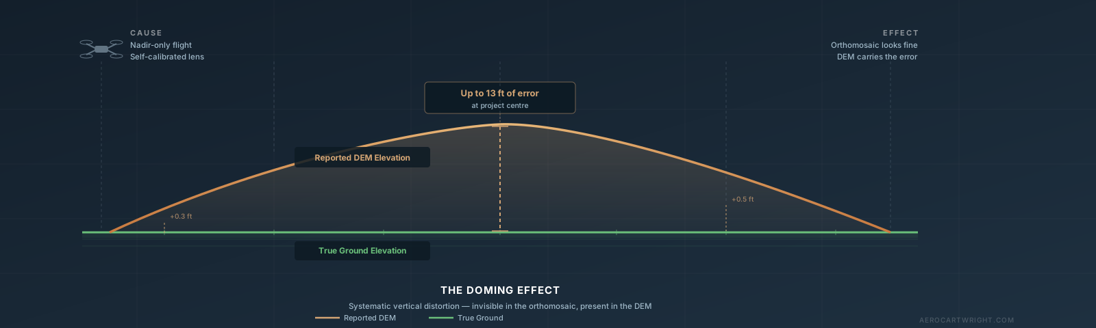
The orthomosaic looks sharp. Your client is satisfied with the preview. Then a field engineer walks the site with an RTK rover and checks a benchmark near the center of your project. The elevation is off by eight inches. You check the corner benchmarks. They’re within 0.05 ft. You pull the DEM and look at a profile across the site. The surface is not flat. It bows upward in the middle by nearly a foot.
Your drone map has the drone map doming effect, and nothing in the deliverable you nearly sent hinted at it.
This is the failure mode that catches pilots off guard: doming is invisible in the orthomosaic, the residuals at your GCP corners can look clean, and you can fly a technically correct mission and still produce a DEM that is systematically wrong. It happens on every photogrammetry platform — Pix4D, Metashape, WebODM — and it happens most often on exactly the flight type most pilots default to: a flat nadir grid over open terrain.
What the Doming Effect Actually Is
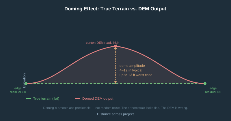
Doming (sometimes called the bowl effect or bowing artifact) is a systematic, large-scale vertical distortion across the entire DEM. The surface appears artificially curved — either the edges sag below the center (bowl) or they rise above it (dome). It is not random noise. It is a smooth, predictable warp that looks like someone inflated or deflated the model from underneath.
The distortion lives almost entirely in the Z axis. Your horizontal positions can be accurate to within a couple of inches while your elevations are off by a foot or more. This drone survey elevation error is invisible in plan view — your orthomosaic can look perfect while your DEM is lying.
Magnitude figures in the first three rows come from simulations in James & Robson (Earth Surface Processes and Landforms, 2014), a widely cited peer-reviewed quantification of dome amplitude. Their simulations assumed a nominal 50 m (~164 ft) flying height, and they report the dome over horizontal distances of about 100 m (~330 ft) from the survey center. The paper calls the simulations “effectively scale independent,” so the absolute dome should grow with flying height and survey extent. The last two rows are not from the paper.
| Flight Scenario | Typical Dome Amplitude |
|---|---|
| Nadir-only, self-calibrated, realistic flight variability | ~8 in (0.2 m) over horizontal distances of ~330 ft (100 m), with 2° camera-pointing and 1 m altitude variability and no control points |
| Nadir-only, self-calibrated, idealized worst case (zero flight variability, flat terrain) | More than 3 ft (1 m) — the paper calls it “metre-magnitude” |
| Nadir + oblique imagery added, practical flight plan | Roughly 0.4–0.8 in (1–2 cm), read from the paper’s Figure 5 — one to two orders of magnitude better |
| Nadir-only, pre-calibrated camera | Negligible in the paper’s simulations when an accurate fixed camera model is used; project-dependent in practice |
| Optimized design + RTK or GCPs | Further reduced — sub-inch residuals are a reasonable field expectation on well-controlled projects (not a figure from the paper) |
A 1-ft dome across a 10-acre construction site looks like survey accuracy in plan view. Your volumes can be wrong by thousands of cubic yards (a 1-ft dome over 10 acres encloses roughly 8,000 cubic yards). The orthomosaic will look fine. The DEM will not.
Why It Happens: The Four Contributors
1. Radial Lens Distortion Misestimation — The Primary Cause
Every camera lens bends light slightly. The Brown-Conrady distortion model uses coefficients (k1, k2, k3) to characterize how much straight lines bow inward or outward near the image edges. Photogrammetry software estimates these coefficients as part of bundle adjustment — the mathematical process that simultaneously solves for camera positions, orientations, and 3D point locations.
Here is where things go wrong on a standard nadir grid: when all your photos are taken nearly straight down, every camera is pointed in roughly the same direction. The bundle adjustment’s Jacobian matrix becomes ill-conditioned — technically, there is no longer enough geometric diversity in the image network to separate true radial distortion from a systematic warp in the surface. The optimizer finds a distortion curve that minimizes reprojection error but is physically wrong, and that incorrect distortion propagates directly into a domed or bowled surface in the output.
This is not a bug in any particular software. It is a geometry problem. The math cannot solve what the image network does not constrain.
2. EXIF GPS Elevation Garbage
The altitude value in your DJI drone’s image metadata is not survey-grade elevation. On non-RTK aircraft it leans heavily on the barometric altimeter, and temperature changes, pressure fluctuations, and flight duration all shift that reading. Users on Pix4D’s forums report vertical offsets of tens of feet relative to true height on non-RTK consumer drones.
What makes this worse: the barometric reading can drift over a flight, which may show up as a false elevation trend in your image geolocations. Bundle adjustment treats these as real positions and can produce a systematically warped output in response. This is a separate problem from lens distortion doming, but the two compound each other.
Never trust vertical positioning from EXIF metadata alone, regardless of what the map preview looks like.
3. Rolling Shutter Distortion
Rolling shutter sensors expose the sensor one row at a time rather than all at once. During the readout period, the drone has moved. The top and bottom of the same image were captured from slightly different positions in space.
DJI does not publish sensor readout times. The figures below are third-party measurements (Pixpro’s screen-flicker test and the OpenDroneMap community readout database), not manufacturer specs:
| Drone | Rolling Shutter Readout | Photogrammetry Impact |
|---|---|---|
| DJI Mavic 2 Pro | ~47–56 ms depending on aspect ratio | Significant at mapping speeds |
| DJI Phantom 4 Pro | Mechanical shutter up to 1/2000 s (~33 ms only if forced to electronic shutter) | Effectively zero with the mechanical shutter |
| DJI Mini 4 Pro | ~16–21 ms at 12 MP; ~43–58 ms at 48 MP | Moderate at 12 MP, high at 48 MP |
| DJI Air 3 / Air 3S | No published or independently measured figure found | Unknown — measure before enabling correction |
| DJI Mavic 3 (consumer) | ~16 ms | Among the lowest listed (similar to Mini 4 Pro at 12 MP); still check Pix4D’s 2-pixel rule |
| DJI Mavic 3E (enterprise) | Mechanical shutter (when enabled in DJI Pilot 2) | Effectively zero |
| DJI Phantom 4 RTK | Mechanical shutter | Effectively zero |
At 51 ms readout, the first and last sensor rows are captured roughly 0.8–1.7 ft (0.26–0.51 m) apart on the ground at 11–22 mph (5–10 m/s). In Pix4D’s published test (Vautherin et al., 2016), rolling shutter modelling cut vertical RMS error on one large dataset from 2.9 ft (88.8 cm) to 6.7 in (16.9 cm).
4. Bundle Adjustment Convergence Failures
Even with good inputs, bundle adjustment can converge to a local minimum that introduces systematic doming. This is more likely when:
- Tie point quality is low (featureless terrain, motion blur, inadequate overlap)
- Front overlap is under 75% or side overlap under 60% (Pix4D’s general minimum; DroneDeploy defaults to 75/65, Metashape recommends 80/60). On flat, featureless ground, Pix4D advises 80% or more both ways
- All photos are nearly parallel — the same geometry problem as nadir-only flights
Why Your Nadir Grid Is Especially at Risk
A standard lawnmower grid is excellent at producing horizontal overlap. It is geometrically degenerate for self-calibration.
Think of it this way: imagine trying to measure the curvature of a lens by only looking through its center. You need edge angles to see the distortion. That is exactly what oblique images provide — viewing geometry that makes radial distortion mathematically separable from surface shape. When every photo points straight down, the optimizer cannot tell the difference between “the lens is distorted” and “the terrain is curved.”
A 2023 ISPRS Archives study (Nikolakopoulos & Kyriou) compared a nadir camera and a five-lens oblique camera over the same university campus: the nadir DSM averaged 11.7 in (29.7 cm) of elevation difference against GNSS points, the oblique DSM 5.8 in (14.6 cm) — about half. Different cameras were used, so treat it as indicative. James & Robson (2014) found that adding oblique images to a nadir block can reduce systematic dome error by up to two orders of magnitude.
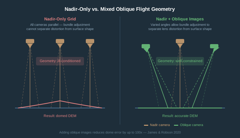
Flat, open terrain is worst. Featureless surfaces like grass fields, agricultural ground, or gravel pads provide weak tie points, so the bundle adjustment has even less geometric information to work with. Complex topography partially self-corrects through stronger image network geometry.
GCPs: Why They Actually Fix the Problem
Ground control points do not just “anchor” the map to real-world coordinates. They break the mathematical degeneracy that causes doming.
The collinearity equation in bundle adjustment ties together three things: camera interior orientation (focal length, principal point, distortion coefficients), camera exterior orientation (position and rotation), and the 3D coordinates of ground points. Without GCPs, all three float freely — and a radial distortion error is geometrically indistinguishable from a domed surface. The optimizer will trade one for the other if it reduces reprojection error.
When you add GCPs, the object coordinates at those locations are fixed. The optimizer can no longer absorb distortion errors as surface errors at control points. It is forced to solve for more accurate distortion coefficients, and the dome shrinks. James & Robson (2014) caution that some residual dome can persist, depending on how precisely the control is weighted, so GCPs reduce the problem rather than guarantee it away.
Minimum effective GCP layout:
- At least 5 GCPs, with one near the center of the block — not just corners
- GCPs at varying elevations when terrain allows (ridge lines, gully edges, low points)
- For larger sites, a rule of thumb (ours, not a published standard) is roughly one GCP per additional 25–30 acres; Pix4D notes 5–10 well-distributed GCPs are usually enough even for large projects
- Corner-only placement is a common mistake — it anchors the perimeter while the center dome continues to grow
GCPs vs. checkpoints: GCPs constrain the adjustment. Checkpoints — surveyed points you withhold from processing — measure residual error independently. A project can show clean GCP residuals while still doming between control points. Always withhold at least 5–6 checkpoints, including one near the center, and inspect for systematic spatial pattern, not just RMS values. That is a working minimum for spotting a dome; a formal ASPRS accuracy statement requires 30.
For step-by-step guidance on setting and surveying GCPs, see How to Set Your Own Ground Control Points for Drone Mapping.
Does a 90-Degree Cross-Flight Actually Help?
Yes — somewhat. Not enough on its own.
Flying a second grid at 90 degrees to the first diversifies camera viewing geometry. Tie points connect images from two different flight directions, giving bundle adjustment stronger geometric constraints. The radial distortion estimate stabilizes.
Some field studies report that cross-flights reduce doming. The catch: both grids are still nadir. The fundamental geometry problem is moderated, not solved. In James & Robson’s (2014) simulations, adding a second set of nadir flight lines at a different heading (offset 20° in their test, with idealized zero-noise flight) did not significantly reduce the dome over flat terrain, while adding oblique images cut it by one to two orders of magnitude. Obliques directly address the viewing-angle degeneracy that nadir-only grids cannot overcome.
Cross-flight is a useful mitigation, not a cure. For complex terrain, cross-flight plus 5 GCPs is a solid combination. For flat open terrain with a precision deliverable, you need GCPs regardless of flight pattern. For the published evidence that oblique imagery fixes doming at the flight-planning stage, see The Doming Myth: Photogrammetry’s Most Fixable Weakness.
Practical note: cross-flights double your flight time and image count. Apps that support double-grid or crosshatch missions on DJI aircraft include DroneDeploy and Dronelink; DJI Pilot 2 offers mapping missions on enterprise aircraft only. DJI Fly has waypoints but no grid planner.
Camera Calibration and Software Settings
Pre-Calibration vs. Self-Calibration
Most software defaults to self-calibration — estimating distortion coefficients from your project’s own images during bundle adjustment. With good geometry, this works. With nadir-only imagery, it is the proximate cause of doming.
Pre-calibration uses camera parameters measured beforehand with a controlled target (checkerboard pattern, calibration wand) and loads them into the software before processing begins. The effect on doming is significant:
- Self-calibration, nadir-only, flat terrain: ~8 in (0.2 m) under realistic flight conditions, more than 3 ft (1 m) in the idealized worst case (James & Robson 2014 simulations)
- Pre-calibration, nadir-only: substantially reduced dome, exact magnitude project-dependent
- Pre-calibration plus RTK or GCPs: further reduced; sub-inch residuals achievable on well-controlled projects
One practical note on consumer DJI cameras: small UAV cameras are sensitive to temperature, as Pix4D notes in its calibration documentation, so a camera cold at takeoff can have different distortion than at operating temperature. As a precaution (a working practice, not a published figure), let the camera run for 2–3 minutes before starting the grid.
Pix4D
Pix4Dmapper ships a camera database with starting internal parameters for common DJI cameras, which it re-optimizes by default. To correct rolling shutter, open Project > Image Properties Editor, edit the camera model, and set Shutter Model to Linear Rolling Shutter, then rerun Initial Processing. Pix4D recommends this when its Vertical Pixel Displacement calculator (a downloadable spreadsheet) returns more than 2. If doming persists, change Internal Parameters Optimization under Processing Options > Initial Processing > Calibration from All to All Prior, which keeps the parameters close to their initial values.
Agisoft Metashape
Run Tools > Optimize Cameras after adding and marking GCPs — not before. The order matters. If you only optimize before adding control, the distortion estimate is never constrained by it; Agisoft says to re-run optimization after adding GCPs.
Enable adaptive camera model fitting for typical nadir aerial blocks. Agisoft’s manual says it helps prevent divergence of poorly constrained parameters in datasets with weak camera geometry.
For pre-calibration, use Metashape’s built-in lens calibration (Tools > Camera > Show Chessboard, then Calibrate Camera; formerly the standalone Agisoft Lens). Load the saved calibration under Tools > Camera Calibration before alignment and tick Fix calibration so it is not re-estimated.
Rolling shutter compensation is enabled in Tools > Camera Calibration (Enable rolling shutter compensation) before the alignment step.
WebODM / OpenDroneMap
Since April 2026, WebODM runs its own engine, ODX, separate from OpenDroneMap’s ODM; both handle rolling shutter the same way. Enable correction with --rolling-shutter. By default the engine looks up readout time in its built-in community database (rollingshutter.py), and --rolling-shutter-readout [ms] overrides it. Cameras not listed fall back to a 30 ms guess. Instructions for measuring your own camera are at github.com/WebODM/RSCalibration (ODX) and github.com/OpenDroneMap/RSCalibration (ODM).
Critical caveat: incorrect readout times make results worse, not just less accurate. In one community forum test on a Mavic 2 Pro, running the correction with a badly wrong readout time (219 ms, taken from a Pix4D estimate, instead of the 56 ms the poster later measured) gave results the poster called “far, far worse” than leaving it disabled. Verify your camera’s actual readout before enabling this flag.
Without GCPs and with nadir-only imagery, ODX and ODM are susceptible to the same doming as any other SfM pipeline. GCPs are the primary mitigation. If you have a trusted pre-calibration (a cameras.json from a calibration flight), pass it with --cameras and add --use-fixed-camera-params so it is held fixed; ODX’s help text says fixing camera parameters can help with doming.
DJI Drone Doming Risk Ranking
Highest consumer risk: DJI Mini 4 Pro — Rolling shutter (electronic only, no mechanical option). DJI publishes no readout time; third-party measurements put it at ~16–21 ms at 12 MP and ~43–58 ms at 48 MP. Consumer EXIF GPS only. Not recommended for vertical deliverables without ground control.
Moderate risk: DJI Air 3 / Air 3S — Rolling shutter with no published or independently measured readout time found, no RTK option, consumer GPS. Requires GCPs for accurate DEMs.
Best consumer option: DJI Mavic 3 (consumer / Mavic 3 Pro) — Hasselblad M4/3 20 MP sensor, ~16 ms rolling shutter readout by third-party measurement — roughly a 3x improvement over the Mavic 2 Pro. Consumer GPS only, so vertical accuracy still depends on GCPs.
Lowest prosumer risk: DJI Mavic 3E (Enterprise) — Mechanical shutter eliminates rolling shutter distortion when it is enabled in DJI Pilot 2. RTK-capable. Disable onboard dewarping for survey work — the in-camera correction crops and resamples the image, which interferes with software-side calibration.
How to Detect Doming Before Delivery
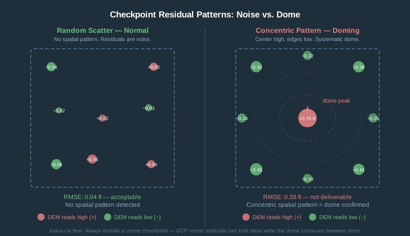
Checkpoint validation is the only reliable way to catch a dome before it becomes your problem.
The method:
- Survey at least 5–6 points (6–10 is better) distributed across the site — include center and corners, not just perimeter — using RTK GPS, a total station, or existing benchmarks.
- Withhold these from GCP processing entirely.
- Process your dataset normally.
- Extract DEM elevation at each checkpoint location.
- Calculate residuals: DEM elevation minus surveyed elevation.
- Look for a spatial pattern.
Random scatter is normal noise. A systematic gradient — center high, edges low, or the reverse — is a dome. The signature is smooth and concentric.
Rule-of-thumb vertical RMSE bands (ours, not ASPRS accuracy classes; your contract’s accuracy class governs):
| Vertical RMSE | Interpretation |
|---|---|
| < 0.1 ft (3 cm) | Survey-grade — excellent |
| 0.1–0.3 ft (3–10 cm) | Acceptable for engineering topography |
| 0.3–1.0 ft (10–30 cm) | Marginal — inspect for systematic dome pattern |
| > 1.0 ft (30 cm) | Too coarse for engineering or survey deliverables |
The trap to avoid: reporting only GCP residuals. GCP residuals tell you how well the model fits the control, not how accurate it is in the areas between control points. Always withhold checkpoints and report both.
For a complete workflow on reaching your first accurate orthomosaic, see Your First Drone Orthomosaic in 90 Minutes.
Tolerance by Job Type
These are conservative working tolerances, not figures from a standard. ASPRS Edition 2 ties legacy 1-ft contours to roughly a 10 cm (0.33 ft) vertical RMSE class and 2-ft contours to roughly 20 cm (0.67 ft).
| Job Type | Vertical Tolerance | Dome That Kills It |
|---|---|---|
| Legal boundary survey | Horizontal standard set by state rules — not a drone-DEM deliverable | N/A |
| Construction volume calculation | ≤ 0.1 ft | > 0.3 ft (about 5–15% error on cuts or fills averaging 1–3 ft deep) |
| Engineering topography, 1-ft contours | ≤ 0.1 ft | > 0.2 ft dome |
| Engineering topography, 2-ft contours | ≤ 0.2 ft | > 0.5 ft dome |
| GIS base mapping / planning | ≤ 1 ft | > 2 ft dome |
| Orthomosaic only, visual inspection | N/A | Doming rarely affects orthomosaic quality |
On volume calculations: a 0.5 ft dome at the center of a 500-ft diameter flat site encloses roughly 1,800 cubic yards of phantom volume (a paraboloid: half the base area times the dome height).
Quick-Reference Action Checklist
Before you process:
- Pre-calibrate camera if delivering to survey tolerances or flying over featureless terrain
- Plan GCP layout with at least one point near the project center
- Withhold at least 5–6 points as checkpoints, including one near the center — do not use them in processing
- Enable rolling shutter correction for any electronic-shutter camera when the expected displacement exceeds about 2 pixels (Pix4D’s rule) — at typical mapping speeds and GSDs that includes most rolling-shutter drone cameras, so run the numbers for your flight
During flight:
- Let the camera run for 2–3 minutes before starting the grid (thermal stabilization — a precaution, not a published figure)
- Maintain at least 75% front and 60% side overlap; on flat, featureless ground go to 80% or more both ways
- Consider cross-flight pattern for flat, featureless terrain
- For oblique passes: add a perimeter flight with the camera tilted 20–30° off nadir (the angles in James & Robson’s 2014 example flight plans). Don’t rely on tilting the whole grid just a few degrees: James et al. (2020) found a gently inclined camera (under 15°) can reduce accuracy when decentring distortion is also estimated
During processing:
- In Metashape: optimize cameras after marking GCPs, not before
- In Pix4D: enable the Linear Rolling Shutter model if the Vertical Pixel Displacement calculator returns more than 2
- In WebODM (ODX) or ODM: confirm your camera is in the engine’s readout database (or measure it) before enabling
--rolling-shutter - Inspect DEM profile before running contours or volumes
Before delivery:
- Calculate checkpoint residuals independently from GCP residuals
- Map residuals spatially — look for concentric pattern, not just RMS
- Apply the tolerance table for your job type
Frequently Asked Questions
What is the drone map doming effect?
The doming effect is a systematic vertical distortion in drone photogrammetry outputs where the DEM surface bows upward in the center or sags at the edges — or vice versa. It is caused primarily by incorrect radial lens distortion estimates produced during bundle adjustment when all flight photos are taken at near-vertical (nadir) angles. The orthomosaic typically looks fine; the elevation model carries the error.
How much elevation error does doming typically cause?
James & Robson (2014) modeled nadir-only, self-calibrated UAV surveys and found dome amplitudes of roughly 8 in (0.2 m) under realistic flight conditions (normal flight-line variability, no control points), rising to more than 3 ft (1 m), which the paper calls “metre-magnitude,” in their idealized worst case (zero flight variability, perfectly parallel passes, flat terrain). The cause is geometry, though the absolute size scales with flying height and survey extent. Adding oblique imagery reduced that error by one to two orders of magnitude in their simulations. Pre-calibration and well-distributed GCPs reduce doming further, though the exact residual is site- and project-dependent rather than a fixed figure. Source: James & Robson 2014, Earth Surface Processes and Landforms.
How do I detect doming before delivering a project?
Survey at least 5–6 checkpoint locations (6–10 is better) across the site (including the center) using RTK GPS or a total station. Withhold these from your GCP processing. After generating the DEM, extract elevations at each checkpoint and compare to surveyed values. If center checkpoints are consistently high and edge checkpoints consistently low (or vice versa), you have a dome. Random scatter is normal noise; a concentric spatial pattern is a dome.
Do GCPs actually fix the doming effect, or just improve overall accuracy?
GCPs directly reduce doming by breaking the mathematical degeneracy that causes it. Without GCPs, the bundle adjustment can compensate for lens distortion errors by warping the surface. When GCP coordinates are fixed, the optimizer can no longer trade a distortion error for a surface error at those locations, forcing the distortion coefficients toward their true values. James & Robson (2014) note some residual dome can remain, depending on how the control is weighted. Corner-only GCP placement is a common mistake — you need at least one near the center of the project block.
Does flying a cross-grid (double-grid) pattern eliminate doming?
It reduces doming but does not eliminate it. Cross-flights diversify the camera viewing geometry, giving bundle adjustment better geometric constraints for self-calibration. Some field studies report an improvement, but it is secondary to adding oblique images or GCPs. Both grids are still nadir, so the fundamental geometry degeneracy is moderated, not resolved. Cross-flight plus 5 well-distributed GCPs is a practical combination for most production mapping jobs.
Which DJI drones are most at risk for the doming effect?
From highest to lowest risk: DJI Mini 4 Pro (rolling shutter, no mechanical option, slow readout in 48 MP mode), DJI Air 3 (rolling shutter, no RTK, no independently measured readout time), DJI Mavic 3 consumer (rolling shutter at about 16 ms by third-party measurement, no RTK), DJI Mavic 3E enterprise (mechanical shutter, RTK-capable — lowest risk). The Mavic 2 Pro sits above the Mavic 3 consumer in risk due to its roughly 47–56 ms rolling shutter readout. None of the consumer rolling-shutter drones are recommended for vertical deliverables without GCPs.
What is the photogrammetry doming fix if I’ve already processed a dataset?
If you have surveyed GCPs you did not use in the original processing, add them and reprocess. In Metashape: import GCPs, mark them in images, then run Tools > Optimize Cameras followed by rebuilding the point cloud and DEM. In Pix4D: add GCPs in Step 1 and reprocess the full pipeline. In WebODM (ODX engine) or ODM: add a GCPs file and reprocess from scratch. If you have no control points and cannot return to the site, there is no software-only fix — the geometry that caused the dome cannot be reconstructed after the fact.
References
Research and standards cited in this article.
- ASPRS. (2024). ASPRS positional accuracy standards for digital geospatial data (Edition 2, Version 2.0). American Society for Photogrammetry and Remote Sensing. doi:10.14358/ASPRS.PAS.2024
- James, M. R., et al. (2020). Mitigating systematic error in topographic models for geomorphic change detection: Accuracy, precision and considerations beyond off-nadir imagery. Earth Surface Processes and Landforms, 45(10), 2251–2271. doi:10.1002/esp.4878
- James, M. R., & Robson, S. (2014). Mitigating systematic error in topographic models derived from UAV and ground-based image networks. Earth Surface Processes and Landforms, 39(10), 1413–1420. doi:10.1002/esp.3609
- Nikolakopoulos, K. G., & Kyriou, A. (2023). Evaluating a nadir and an oblique camera for 3D infrastructure (city) model generation. International Archives of the Photogrammetry, Remote Sensing and Spatial Information Sciences, XLVIII-1/W3-2023, 131–136. doi:10.5194/isprs-archives-XLVIII-1-W3-2023-131-2023
- Vautherin, J., et al. (2016). Photogrammetric accuracy and modeling of rolling shutter cameras. ISPRS Annals of the Photogrammetry, Remote Sensing and Spatial Information Sciences, III-3, 139–146. doi:10.5194/isprs-annals-III-3-139-2016